Shrinking Raspbian OS Image


I’ve been using Raspberry Pi for my projects and have many Raspbian OS image backups. It’s eating up storage space on my PC, so I decided to shrink those images so that I can create more space. I’ve found several sites explain how to do it and writing this post mostly for myself to repeat the process since it’s a little complicated.

If you will follow the steps, please do so at your own risk. Manipulating partition may cause damage to your system.


Contents
– Assumptions
– Steps
1. Find out SD card mount points on your PC
2. Create OS image from SD card
3. Shrink root partition
4. Update partition table
5. Trim empty space from the image file
– Summary
– Reference


Assumptions

Hardware

  • Linux PC (I used Ubuntu 16.04)
  • Micro-SD card reader like this (in case your PC doesn’t have SD card slot)
  • Micro-SD card which contains Raspbian OS you want to shrink

Software

  • GParted (Partition management tool)
    If it’s not installed on your PC, please do so.
sudo apt-get install gparted -y


Steps
1. Find device name of SD card on your PC
1-1. Before insert SD card into your PC, check all the mounted devices by typing:

df -h

Output should be like this:

$ df -h
Filesystem      Size  Used Avail Use% Mounted on
udev            1.9G     0  1.9G   0% /dev
tmpfs           385M  6.2M  379M   2% /run
/dev/sda1       290G   24G  252G   9% /
tmpfs           1.9G   24M  1.9G   2% /dev/shm
tmpfs           5.0M  4.0K  5.0M   1% /run/lock
tmpfs           1.9G     0  1.9G   0% /sys/fs/cgroup
tmpfs           385M   68K  385M   1% /run/user/1000

1-2. Then, insert the SD card and check it again.

$ df -h
Filesystem      Size  Used Avail Use% Mounted on
udev            1.9G     0  1.9G   0% /dev
tmpfs           385M  6.2M  379M   2% /run
/dev/sda1       290G   24G  252G   9% /
tmpfs           1.9G   24M  1.9G   2% /dev/shm
tmpfs           5.0M  4.0K  5.0M   1% /run/lock
tmpfs           1.9G     0  1.9G   0% /sys/fs/cgroup
tmpfs           385M   68K  385M   1% /run/user/1000
/dev/sdb2        30G  3.3G   25G  12% /media/max/037616fd-28fe-4652-8248-2042ea30b929
/dev/sdb1        42M   21M   21M  51% /media/max/boot

1-3. Compare the outputs. Since Raspbian has two partitions, there should be two new lines added. In the example above, /dev/sdb1 and /dev/sdb2. Also, the device name of the SD card is /dev/sdb. The last character in a mount point represents the partition number.


2. Create OS image from SD card
2-1. First, unmount the partitions.

sudo umount /dev/sdb1 /dev/sdb2

2-2. Copy the image from SD card to PC. In the below example, please replace “/dev/sdb” with device name which you found out in above steps, and “raspbian.img” with anything you want for the file name on your PC.

sudo dd bs=4M if=/dev/sdb of=raspbian.img status=progress conv=fsync

2-3. Change owner of the newly created image file.

sudo chown $USER:$USER raspbian.img


3. Shrink root partition
3-1. Raspbian has two partitions, “boot” and “root”. “boot” is very small and it’s not worth to compress. So, let’s find out the start sector of “root” partition by typing:

fdisk -l raspbian.img

The output should be like this. Take a note of value of “Start” of the bigger partition. It’s start sector of “root” partition. In example below, it’s “94208”.

$ fdisk -l raspbian.img
Disk raspbian.img: 29.7 GiB, 31914983424 bytes, 62333952 sectors
Units: sectors of 1 * 512 = 512 bytes
Sector size (logical/physical): 512 bytes / 512 bytes
I/O size (minimum/optimal): 512 bytes / 512 bytes
Disklabel type: dos
Disk identifier: 0xede1dcd1

Device        Boot Start      End  Sectors  Size Id Type
raspbian.img1       8192    93814    85623 41.8M  c W95 FAT32 (LBA)
raspbian.img2      94208 62333951 62239744 29.7G 83 Linux

3-2. Create a loopback device with the Raspbian image so that GParted can recognize the image as device. Please replace “94208” with the value you got in previous step.

sudo losetup /dev/loop0 raspbian.img -o $((94208*512))

3-3. Launch GParted.

sudo gparted /dev/loop0

It will open a new window.

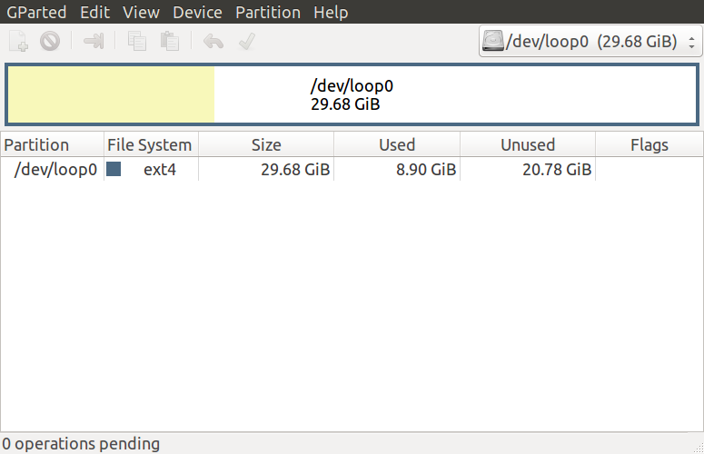
3-4. Click “/dev/loop0” and select “Partition” > “Resize/Move”.

3-5. Then, change “New size” of the image.
Note: This step is a little tricky. It seems it requires some margin but I couldn’t figure out how much margin it exactly requires. Seems it differs based on the “Minimum size”. I needed to do trial-and-error till successfully complete resizing.

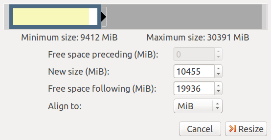
3-6. Click on “Resize” button.

3-7. Select “Edit” > “Apply All Operations”.
Note : If you get “resize2fs: New size smaller than minimum” error, go back to step 3-4.

3-8. Click on “Save Details”.

3-9. Open saved “gparted_details.htm” file on browser and search a line starts with “resize2fs”. The value followed by “K” is new size for “root” partition. Take a note of this value. In example below, it’s “4934656K”.

resize2fs -p /dev/loop0 4934656K  00:00:00    ( SUCCESS )

3-10. Click on “Close” button and close GParted.

3-11. Remove the loopback device.

sudo losetup -d /dev/loop0


4. Update partition table
4-1. Create a new loopback device for the whole image

sudo losetup /dev/loop0 raspbian.img

4-2. Launch fdisk to update partition table.

sudo fdisk /dev/loop0

4-3. Delete 2nd partition (i.e. root partition).
4-3-1. Type “d” and enter.

Command (m for help): d

4-3-2. Type “2” and enter to select 2nd partition.

Partition number (1,2, default 2): 2

4-4. Create new 2nd partition.
4-4-1. Type “n” and enter to create new partition.

Command (m for help): n

4-4-2. Type “p” and enter to make it a primary partition.

Select (default p): p

4-4-3. Type “2” and enter to select partition number.

Partition number (2-4, default 2): 2

4-4-4. Enter the start sector of 2nd partition. (See step 3-1)

First sector (2048-31116287, default 2048): 94208

4-4-5. Type “+” and the new size for 2nd partition (see step 3-9).

Last sector, +sectors or +size{K,M,G,T,P} (94208-62333951, default 62333951): +4934656K

4-5. Apply all the changes by typing “w” and enter.

Command (m for help): w

Then you’ll get a warning message like below but you can ignore it.

The partition table has been altered.
Calling ioctl() to re-read partition table.
Re-reading the partition table failed.: Invalid argument

The kernel still uses the old table. The new table will be used at the next reboot or after you run partprobe(8) or kpartx(8).


5. Trim empty space from the image file
5-1. Find out the end sector of the 2nd partition by using fdisk.

sudo fdisk -l /dev/loop0

The output should be like this:

$ sudo fdisk -l /dev/loop0
Disk /dev/loop0: 29.7 GiB, 31914983424 bytes, 62333952 sectors
Units: sectors of 1 * 512 = 512 bytes
Sector size (logical/physical): 512 bytes / 512 bytes
I/O size (minimum/optimal): 512 bytes / 512 bytes
Disklabel type: dos
Disk identifier: 0x366b9010

Device       Boot Start     End Sectors  Size Id Type
/dev/loop0p1       8192   93814   85623 41.8M  c W95 FAT32 (LBA)
/dev/loop0p2      94208 9963519 9869312  4.7G 83 Linux

Note down the end sector value of 2nd partition. (i.e. “9963519”)

5-2. Remove the loopback device.

sudo losetup -d /dev/loop0

5-3. Trim the empty space from the image file. Please replace “9963519” in the example below with your end sector value from the previous step.

truncate -s $(((9963519+1)*512)) raspbian.img

That’s it. Now the Raspbian image has been shrinked. In the example below, the size is now 1.8 GB. (originally it’s 30 GB)

$ ls -lh raspbian.img 
-rw-r--r-- 1 max max 4.8G Sep 10 21:36 raspbian.img


Summary
It’s not very easy but it can definitely reduce the size of the SD card image. If you want more free space on your PC, you can zip the image file.

zip raspbian.zip raspbian.img

Here is an example (32 GB SD card) of comparison between before, after, and after + zip.

-rw-r--r-- 1 max max 30G Sep 6 16:19 raspbian-before.img
-rw-r--r-- 1 max max 4.8G Sep  6 19:18 raspbian-after.img
-rw-rw-r-- 1 max max 1.9G Sep  6 19:22 raspbian-after.zip


To write Raspbian image (.img or .zip) to SD card, please see this.


Reference
– Shrinking Raspberry Pi SD Card Images
http://www.aoakley.com/articles/2015-10-09-resizing-sd-images.php

– How to BackUp and Shrink Your Raspberry Pi Image
http://www.instructables.com/id/How-to-BackUp-and-Shrink-Your-Raspberry-Pi-Image/

– Installing operating system images on Linux
https://www.raspberrypi.org/documentation/installation/installing-images/linux.md


Writing Raspbian OS Image to SD Card on Linux


This is how to write Raspbian OS image to SD card by using Linux command line. Since the steps below use “dd” command which may cause damage to your system if used wrongly, please be careful about the usage.


Contents
– Assumptions
– Steps
1. Download Raspbian OS Image
2. Find device name of SD card on Linux
3. Write Raspbian OS image to SD card
– Reference


Assumptions

  • Raspberry Pi board
  • Micro SD card
  • Linux PC
  • Micro SD card adapter


Steps
1. Download Raspbian OS Image
1-1. Download Raspbian OS zip archive from the official site to your Linux PC.


2. Find device name of SD card on Linux
2-1. Before insert SD card into your PC, check all the mounted devices by typing:

df -h

Output should be like this:

$ df -h
Filesystem      Size  Used Avail Use% Mounted on
udev            3.9G     0  3.9G   0% /dev
tmpfs           789M  9.5M  780M   2% /run
/dev/sda1       451G   17G  412G   4% /
tmpfs           3.9G   61M  3.8G   2% /dev/shm
tmpfs           5.0M  4.0K  5.0M   1% /run/lock
tmpfs           3.9G     0  3.9G   0% /sys/fs/cgroup
tmpfs           789M   72K  789M   1% /run/user/1000

2-2. Then, insert the SD card and check it again.

$ df -h
Filesystem      Size  Used Avail Use% Mounted on
udev            3.9G     0  3.9G   0% /dev
tmpfs           789M  9.5M  779M   2% /run
/dev/sda1       451G   17G  412G   4% /
tmpfs           3.9G   61M  3.8G   2% /dev/shm
tmpfs           5.0M  4.0K  5.0M   1% /run/lock
tmpfs           3.9G     0  3.9G   0% /sys/fs/cgroup
tmpfs           789M   72K  789M   1% /run/user/1000
/dev/sdb2        30G  8.4G   20G  31% /media/max/037616fd-28fe-4652-8248-2042ea30b929
/dev/sdb1        42M   21M   21M  51% /media/max/boot

2-3. Compare the outputs. Newly added device is for the SD card. Since the last part (“1”) is the partition number, the device name for whole SD card is /dev/sdb. Take a note of the device name.

2-4. Unmount the SD card partition(s). Type below, replacing /dev/sdb1 with your SD card device name.

umount /dev/sdb1


3. Write Raspbian OS image to SD card
3-1. Type below to unzip the archive and write it to SD card. Please replace “2017-08-16-raspbian-stretch.zip” with the file name of your OS image archive and “/dev/sdb” with your SD card device (see step 2-3).

unzip -p 2017-08-16-raspbian-stretch.zip | sudo dd of=/dev/sdb bs=4M status=progress conv=fsync

In case you are writing .img file, type below:

sudo dd bs=4M if=2017-08-16-raspbian-stretch.img of=/dev/sdb status=progress conv=fsync


Reference
– INSTALLING OPERATING SYSTEM IMAGES ON LINUX
https://www.raspberrypi.org/documentation/installation/installing-images/linux.md

– RPi Easy SD Card Setup
http://elinux.org/RPi_Easy_SD_Card_Setup


Enabling Hands-Free Profile on Raspberry Pi (Raspbian Stretch) by using PulseAudio


The purpose of this post is to enable Bluetooth Handsfree Profile (HFP) with PulseAudio on Raspbian Stretch so that Raspberry Pi can act like as a handsfree speaker phone or a handsfree car kit. This is an updated version of this post. When I wrote the previous post, I was using Raspbian Jessie and some steps needed to be updated to apply Raspbian Stretch.

There is one thing needs to be mentioned before start. The original plan was to use Raspberry Pi3’s on-board Bluetooth chip for this project. Unfortunately, it didn’t work. It seems that the problem is related with the chip. So, we have to use a Bluetooth dongle instead.


Here is the list of contents of this post.

Contents
– Prerequisites
– Steps
1. Preparations
2. oFono Installation
3. PulseAudio Installation & Settings
4. Connecting Your Phone
5. Making a Call
– Summary
– Reference


Prerequisites

Below are the required application versions to enable Bluetooth HFP according to PulseAudio release note.

  • Bluez 5.0 or later (v5.43 is pre-installed in Stretch)
  • PulseAudio 6.0 or later (not pre-installed in Stretch, but it supports v10.0)
  • oFono 1.13 or later (not pre-installed in Stretch, but it supports v1.18)


Steps
1. Preparations
1-1. Connect Bluetooth dongle and USB sound card with Raspberry Pi.
1-2. Connect the microphone and speakers to 3.5 mm audio jacks on the USB sound card.
1-3. Boot up Raspberry Pi Board.
1-4. As described, we don’t use on-board Bluetooth chip. So we’ll disable it. To do that, open “/etc/modprobe.d/raspi-blacklist.conf”.

sudo nano /etc/modprobe.d/raspi-blacklist.conf

1-5. Add lines below and save.

blacklist btbcm
blacklist hci_uart

1-6. According to a Raspberry Pi Foundation blog post, Bluetooth audio is handled by ALSA through bluez-alsa in Stretch. However, since in this post we are using PulseAudio, let’s uninstall bluez-alsa.

sudo apt-get purge bluealsa -y

1-7. Then reboot the board.

sudo reboot

1-8. After reboot, check dmesg and make sure there is no Bluetooth-related errors.

dmesg | grep -i bluetooth

1-9. Also, make sure hci0 is UP.

hciconfig

The result should be like this:

hci0:    Type: BR/EDR  Bus: USB
    BD Address: XX:XX:XX:XX:XX:XX  ACL MTU: 310:10  SCO MTU: 64:8
    UP RUNNING
    RX bytes:622 acl:0 sco:0 events:38 errors:0
    TX bytes:1437 acl:0 sco:0 commands:38 errors:0

If it’s DOWN for some reason, then turn it up.

sudo hciconfig hci0 up


2. oFono Installation
2-1. oFono is not installed by default, so let’s install it.

sudo apt-get install ofono -y

2-2. Make sure if it’s successfully installed.

$ ofonod --version
1.18

2-2. Then, start the service.

sudo systemctl start ofono

You can check the service running like below.

$ systemctl -a |grep ofono
  ofono.service     loaded    active   running   Telephony service


3. PulseAudio Installation & Settings
3-1. In Raspbian Stretch, PulseAudio is not pre-installed. Install PulseAudio and its Bluetooth module:

sudo apt-get install pulseaudio pulseaudio-module-bluetooth -y

3-2. Check the version. It should be v10.0 (or higher).

$ pulseaudio --version
pulseaudio 10.0

3-3. Open “/etc/pulse/default.pa”.

sudo nano /etc/pulse/default.pa

3-4. Add “headset=ofono” on the line of ‘module-bluetooth-discover’.

load-module module-bluetooth-discover headset=ofono

3-5. Restart Raspberry Pi.

sudo reboot


4. Connecting Your Phone
4-1. Launch bluetoothctl.

bluetoothctl

4-2. Then, input below commands.

power on
agent on
default-agent

4-3. Start searching your phone. Make sure your phone is discoverable.

scan on

4-4. After detecting your phone, turn scan off.

scan off

devices command shows a list of found devices.

[bluetooth]# devices
Device XX:XX:XX:XX:XX:XX Galaxy S7

4-5. Then, pair, trust and connect to your phone by specifying the Bluetooth device address (in this case it’s “XX:XX:XX:XX:XX:XX”, please replace it wity your device’s address).

pair XX:XX:XX:XX:XX:XX
trust XX:XX:XX:XX:XX:XX
connect XX:XX:XX:XX:XX:XX

If everything is ok, you should see “successful” at the end of the result for each command like below.

[bluetooth]# pair XX:XX:XX:XX:XX:XX
...
Pairing successful
[bluetooth]# trust XX:XX:XX:XX:XX:XX
...
trust succeeded
[bluetooth]# connect XX:XX:XX:XX:XX:XX
...
Connection successful


5. Making a Call
To make a call, you can use oFono test scripts which is included in the source code.
5-1. First, download the source and extruct.

wget https://www.kernel.org/pub/linux/network/ofono/ofono-1.18.tar.gz
tar -xzvf ofono-1.18.tar.gz

5-2. Then, you can make a call by:

python ./ofono-1.18/test/dial-number 8586515050

If you want to end the call, then type:

python ./ofono-1.18/test/hangup-active


Summary
Since Raspbian Stretch supports PulseAudio v10.0, the steps are now a little simpler than previous one. I confirmed both sending and receiving audio are fine during a hands free call. I confirmed Bluetooth audio streaming (A2DP) is working too.


Update (May 2, 2018):
The steps to enable equalizer on HFP sending audio is newly posted.


Reference

– Raspbian Stretch has arrived for Raspberry Pi
https://www.raspberrypi.org/blog/raspbian-stretch/

– Connect Bluetooth Headset To Raspberry Pi 3 (A2DP & HSP)
http://youness.net/raspberry-pi/bluetooth-headset-raspberry-pi-3-ad2p-hsp

– PulseAudio 6.0 Release Notes –freedesktop.org
https://www.freedesktop.org/wiki/Software/PulseAudio/Notes/6.0/

– PulseAudio Documentation –freedesktop.org
https://freedesktop.org/wiki/Software/PulseAudio/Documentation/


Headless Setup for Raspberry Pi 3 and Raspberry Pi Zero W


This is an initial setup steps to create a headless Raspberry Pi 3 B+ or Raspberry Pi Zero W (Wireless). It enables access to Raspberry Pi’s console without having a dedicated keyboard, mouse, or display. A PC and Wi-Fi network is required since we’ll access to the console from PC using ssh over Wi-Fi.


Contents
– Prerequisites
– Steps
1. Burn Raspbian OS on micro SD card
2. Enable SSH
3. Enable Wi-Fi access
4. Boot up Raspberry Pi board
5. Check Raspberry Pi’s IP address
6. Access to Raspberry Pi via SSH


Prerequisites

  • Raspberry Pi board (Raspberry Pi 3 B+ or Pi Zero W)
  • Micro SD card
  • Micro SD card reader like this (in case your PC doesn’t have SD card slot)
  • PC (for burning the OS image, accessing to Raspberry Pi via ssh)
  • Micro USB cable for power supply


Steps
1. Burn Raspbian OS on micro SD card
Follow the official instruction to prepare OS image in a SD card.


2. Enable SSH
2-1. After finishing writing OS image, open the created “boot” partition.

2-2. Create an empty file with name “ssh”.


3. Enable Wi-Fi access
In the same partition, create a file named “wpa_supplicant.conf” with lines below. Please replace <SSID> and <PASSWORD> with your own Wi-Fi network name and password.

ctrl_interface=DIR=/var/run/wpa_supplicant GROUP=netdev
update_config=1
country=US

network={
	ssid="<SSID>"
	psk="<PASSWORD>"
	key_mgmt=WPA-PSK
}


4. Boot up Raspberry Pi board
4-1. Eject the micro SD card from PC and insert it into Raspberry Pi

4-2. Connect Micro USB Power Cable and boot Raspberry up.


5. Check Raspberry Pi’s IP address
Find out Raspberry Pi’s IP address to access via ssh. I used “nmap” command on Linux PC.

Note: You need to specify netmask of your own Wi-Fi network.

nmap -sn 192.168.1.0/24

Output:

$ nmap -sn 192.168.1.0/24

Starting Nmap 7.01 ( https://nmap.org ) at 2017-09-04 17:35 EDT
Nmap scan report for 192.168.1.1
Host is up (0.032s latency).
Nmap scan report for 192.168.1.141
Host is up (0.049s latency).
Nmap scan report for 192.168.1.142
Host is up (0.00017s latency).
Nmap done: 256 IP addresses (3 hosts up) scanned in 2.83 seconds


6. Access to Raspberry Pi via SSH
ssh from PC to the IP address you found out.

ssh pi@192.168.1.141


Qt Creator Cross Compiling Environment for Raspberry Pi3 with QtRpi


Update (June 2, 2018):
If you are using Raspbian Stretch, please check this post. The steps below are for Raspbian Jessie.


This is the steps how I created Qt Creator cross compiling environment on Ubuntu PC for Raspberry Pi 3 B+ by using QtRpi. Thanks to QtRpi, it’s pretty straightforward. I followed the official site and its GitHub page. The purpose of this post is mostly for myself, to reproduce the steps in future (on other PCs or when I need to reinstall, etc).


Here is the list of contents of this post.

Contents
– Assumptions
– Steps
1. Preparation
2. Install Qt
3. Deploy Qt to Raspberry Pi
4. Qt Creator Configuration
5. Verify Cross Compiling Environment
– Troubleshoot
– Reference


Assumptions
Here are some assumptions before starting the steps:

– Ubuntu Linux running on host PC
– Raspbian running on the target Raspberry Pi 3 B+
– Qt Creator running on host PC
– SSH access from host PC to target Raspberry Pi

In the steps below, I used following:

Ubuntu 16.04 as host
Raspbian Jessie (2017-07-05) running on Raspberry Pi 3 as target
Qt Creator 4.3.1 running on host


Steps
1. Preparation
1-1. Install dependencies

sudo apt-get install curl g++ gdb-multiarch git realpath unzip zip -y

1-2. Configure environment variables
In my case, the environment variables are below since Qt version is 5.7.0 and target device is Raspberry Pi 3. In case you use different version or device, click here and see “2. Configure your environment variables” for other options.

export QTRPI_QT_VERSION='5.7.0'
export QTRPI_TARGET_DEVICE='linux-rpi3-g++'

Also, set your target’s IP address.

export QTRPI_TARGET_HOST='pi@192.168.0.5'

1-3. Password less SSH login
Generate SSH key and copy it to the target so that you can log in without requiring a password.

ssh-keygen

Just press enter when you asked about pass phrase.  Then, copy the key by typing:

ssh-copy-id $QTRPI_TARGET_HOST


2. Install Qt
The beauty of QtRpi is that scripts will take care of all the installation and deployment.

2-1. First, clone QtRpi from GitHub.

git clone https://github.com/neuronalmotion/qtrpi.git

2-2. Then run “init-qtrpi-minimal.sh” script. This will take a while.

cd qtrpi
./init-qtrpi-minimal.sh


3. Deploy Qt to Raspberry Pi
3-1. Run “./deploy-qtrpi.sh” to deploy Qt

./deploy-qtrpi.sh --prepare-rpi

3-2. This step is a workaround for font display. (see troubleshoot section for detail.)
3-2-1. Login to Raspberry Pi.

ssh $QTRPI_TARGET_HOST

3-2-2. Copy font files.

cp -r /usr/share/fonts/truetype/dejavu /usr/local/qt5pi/lib/fonts


4. Qt Creator Configuration
To cross-compile and deploy from Qt Creator SDK, some configurations are required.

4-1. Device Configuration
4-1-1. Launch Qt Creator on host.
4-1-2. Navigate to “Tools” > “Options…”
4-1-3. In Options window, select “Devices” from left side bar.
4-1-4. Select “Add…”
4-1-5. Double click on “Generic Linux Device”

4-1-6. Enter information below into “New Generic Linux Device Configuration Setup” window.
Configuration name : Rpi 3
IP address : 192.168.0.5
Username : pi
Authentication type : Key

4-1-7. Click on “Next”, Then “Finish”. Then, it will automatically start “Device Test”.
4-1-8. Click “Close” to close “Device Test” window.
4-1-9. Click “Apply” on “Options” window (just in case?)

4-2. Debuggers
4-2-1. In Options window, select “Build & Run” from left side bar.
4-2-2. Click on “Debuggers” tab
4-2-3. Click on “Add” button
4-2-4. Put information below:
Name: GDB multiarch
Path : /usr/bin/gdb-multiarch

4-2-5. Click on “Apply”

4-3. Compilers
4-3-1. Click on “Compilers” tab
4-3-2. Navigate to “Add” > “GCC” > “C”
4-3-3. Enter information below:
Name: GCC rpi
Compiler Path: /opt/qtrpi/raspi/tools/arm-bcm2708/gcc-linaro-arm-linux-gnueabihf-raspbian-x64/arm-linux-gnueabihf/bin/gcc

4-3-4. Click on “Apply” button
4-3-5. Navigate to “Add” > “GCC” > “C++”
4-3-6. Enter information below:
Name :G++ rpi
Compiler Path:/opt/qtrpi/raspi/tools/arm-bcm2708/gcc-linaro-arm-linux-gnueabihf-raspbian-x64/arm-linux-gnueabihf/bin/g++

4-3-7. Click on “Apply” button

4-4. Qt Versions
4-4-1. Click on “Qt Versions” tab
4-4-2. Click on “Add…”
4-4-3. Navigate qmake path to “/opt/qtrpi/raspi/qt5/bin/qmake”
4-4-4. Enter “Qt rpi %{Qt:Version}” as “Version name”.

4-4-5. Click on “Apply” button

4-5. Kits
4-5-1. Click on “Kits” tab
4-5-2. Click on “Add” button
4-5-3. Enter (or select) information below:
Name : Rpi 3
Device Type: Generic Linux Device
Sysroot : /opt/qtrpi/raspbian/sysroot
Compiler: C: GCC rpi
Compiler: C++: G++ rpi
Debugger : GDB multiarch
Qt Version : Qt rpi 5.7.0

4-5-4. Click on “Apply” button, then “OK”.


5. Verify Cross Compiling Environment
Let’s check if everything is OK by building a sample project on host and executing it on RPi.

5-1. “File” > “New File or Project”
5-2. “Application” > “Qt Qucick Controls 2 Application”, then click on “Choose…” button.
5-3. Enter project name and click on “Next”.
5-4. Click on “Next” on “Define Build System” and “Define Project Details”.
5-5. Check on “Rpi 3” on “Kit Selection”.
5-6. Click on “Finish” button on “Project Management”.
5-7. Open .pro file from project tree.
5-8. Add two lines below at the end of the file and save it.

target.path = /home/pi/
INSTALLS += target

5-9. Select “Projects” icon on left side bar.
5-10. Click on “Rpi 3” under “Build & Run”.
5-11. Click on “Run” icon on the left side bar.


Troubleshoot
Originally, I’ve added the following environment variables to ~/.bashrc on Raspberry Pi after deploying Qt to Raspberry Pi based on video on official site.

export QT_QPA_EGLFS_PHYSICAL_WIDTH=528
export QT_QPA_EGLFS_PHYSICAL_HEIGHT=295
export QT_QPA_FONTDIR=/usr/share/fonts/truetype/dejavu/

However, when I run a program from Qt Creator on host PC, it seems that those variables are not set and no font is displayed on the application window. (getting below messages in “Application Output” on Qt Creator.) If I launch the same application from Raspberry Pi’s console, the issue doesn’t happen.

QML debugging is enabled. Only use this in a safe environment.
Unable to query physical screen size, defaulting to 100 dpi.
To override, set QT_QPA_EGLFS_PHYSICAL_WIDTH and QT_QPA_EGLFS_PHYSICAL_HEIGHT (in millimeters).
QFontDatabase: Cannot find font directory /usr/local/qt5pi/lib/fonts.
Note that Qt no longer ships fonts. Deploy some (from http://dejavu-fonts.org for example) or switch to fontconfig.

I’ve not been able to figure out the cause but found a workaround (step 3-2 above).


Reference
– QtRpi FAQ
http://www.qtrpi.com/faq#howtohttps://github.com/neuronalmotion/qtrpiinstall

– GitHub
https://github.com/neuronalmotion/qtrpi