Controlling Display Backlight on Raspberry Pi


This is how to turn on and off backlight on Raspberry Pi for the official 7-inch touchscreen display and HDMI displays using command-line interface (CLI).

I checked it with Raspberry Pi 3 B+ running Raspbian Stretch (September 2017 version) + official 7″ display / GeChic 1002 10.1″ HDMI Display.


The official 7-inch touchscreen display [1]

OFF:

echo 1 | sudo tee /sys/class/backlight/rpi_backlight/bl_power

ON:

echo 0 | sudo tee /sys/class/backlight/rpi_backlight/bl_power


HDMI displays [2] [3] [4]

OFF:

vcgencmd display_power 0

ON:

vcgencmd display_power 1


Troubleshoot

You may get the error below if you are using older software.

-bash: /sys/class/backlight/rpi_backlight/brightness: No such file or directory

In that case, run rpi-update. [5]

sudo rpi-update


Summary [6]

Since I use both the official 7″ display and the HDMI display, I wrote a script which works for both displays.

Note: It’s working on my environments but I don’t think how it detects HDMI connection (i.e. line 10) is robust enough. You should test with “tvservice -s” command on your environment.

rpi-backlight:

#!/bin/bash

if [ $# -eq 0 ] || [[ $1 != "on"  &&  $1 != "off" ]]; then
  echo "Usage: rpi-backlight [on/off]"
  exit 1
fi

output=$(tvservice -s)

if [[ $output =~ "0x400000 [LCD]" ]]; then

  # Official 7" display
  if [ $1 = "on" ]; then
    echo 0 | sudo tee /sys/class/backlight/rpi_backlight/bl_power
  elif [ $1 = "off" ]; then
    echo 1 | sudo tee /sys/class/backlight/rpi_backlight/bl_power
  fi

else

  # HDMI display
  if [ $1 = "on" ]; then
    vcgencmd display_power 1
  elif [ $1 = "off" ]; then
    vcgencmd display_power 0
  fi

fi


References
[1] Official 7” Raspberry Pi Touch Screen FAQ

[2] Programmatically turn screen off

[3] Turning ‘tvservice’ on and off leaves screen blank

[4] RPI vcgencmd usage

[5] RPi Touchscreen – How to turn it off?

[6] Detect HDMI and Start GUI


Silent boot on Raspbian Stretch/Buster

The purpose of the steps here is to remove 1 – 4 below from showing up at Raspberry Pi boot up process. After following the steps, the first thing you see will be Raspbian desktop.

1) Rainbow image
2) Raspberry Pi Logo (image of four raspberries at the top left corner)
3) Blinking cursor (at the top left corner)
4) Splash image

I tested the steps with the following setup:


Steps
1. Remove Rainbow Screen
1-1. Open “/boot/config.txt”.

sudo nano /boot/config.txt

1-2. Then add below at the end of the file.

# Disable rainbow image at boot
disable_splash=1


2. Disable splash image
2-1. Disable (mask) plymouth services.

sudo systemctl mask plymouth-start.service


3. Remove Raspberry Pi logo and blinking cursor
3-1. Open “/boot/cmdline.txt”.

sudo nano /boot/cmdline.txt

3-2. Add below at the end of the line.

logo.nologo vt.global_cursor_default=0

‘logo.nologo’ and ‘vt.global_cursor_default=0’ remove Raspberry Pi logo and blinking cursor, respectively.


4. Verify
Reboot the board and see if it works properly.

sudo reboot


In case a lightning bolt icon is shown in the right-top corner of the screen, see this post.


Disabling IPv6 Kernel Module on Raspbian Stretch

I’m using Raspbian Stretch Lite (September 2017 version) and for some reason, wanted to disable IPv6 kernel module, which is loaded by default. Basically, it can be done by blacklisting the kernel module. [1]

Here is steps I took.


1. Check already loaded modules (Optional)
You can check already loaded modules by ‘lsmod’ command. IPv6 appears at the last line of the example below.

pi@raspberrypi:~ $ lsmod
Module                  Size  Used by
cmac                    3239  1
bnep                   12051  2
hci_uart               20020  1
btbcm                   7916  1 hci_uart
bluetooth             365511  24 hci_uart,bnep,btbcm
brcmfmac              223048  0
brcmutil                9092  1 brcmfmac
cfg80211              543091  1 brcmfmac
rfkill                 20851  6 bluetooth,cfg80211
bcm2835_gpiomem         3940  0
evdev                  12423  0
joydev                  9988  0
fixed                   3285  0
uio_pdrv_genirq         3923  0
uio                    10204  1 uio_pdrv_genirq
hid_multitouch         11312  0
ip_tables              13161  0
x_tables               20578  1 ip_tables
ipv6                  409035  22


2. Blacklist IPv6 kernel module
Open the configuration file,

sudo nano /etc/modprobe.d/ipv6.conf

and add the line below.

blacklist ipv6

Save, and close.


3. Reboot
Restart the system to unload the kernel module.

sudo reboot


4. Verify
Check the loaded modules again. ‘ipv6’ should be gone if everything is done properly.

pi@raspberrypi:~ $ lsmod
Module                  Size  Used by
cmac                    3239  1
bnep                   12051  2
hci_uart               20020  1
btbcm                   7916  1 hci_uart
bluetooth             365511  24 hci_uart,bnep,btbcm
brcmfmac              223048  0
brcmutil                9092  1 brcmfmac
cfg80211              543091  1 brcmfmac
rfkill                 20851  6 bluetooth,cfg80211
bcm2835_gpiomem         3940  0
evdev                  12423  0
fixed                   3285  0
uio_pdrv_genirq         3923  0
joydev                  9988  0
uio                    10204  1 uio_pdrv_genirq
hid_multitouch         11312  0
ip_tables              13161  0
x_tables               20578  1 ip_tables


References
1. How to disable loading of unnecessary kernel modules


Setting Up UART Serial Communication between Raspberry Pi and PC


This post shows how to setup serial communication between Raspberry Pi and PC using a USB-Serial cable.

Here is the list of contents of this post.

Contents


Prerequisites
These are required things for this post.

  • Raspberry Pi board : Any Raspberry Pi should work. In this post, Raspberry Pi 3 B+ running Raspbian Stretch is used.
  • PC : The other endpoint. In this post, a Windows 10 PC is used.
  • USB-serial cable : USB to Serial UART converter cable such as this. Make sure the signal voltage level is correct.
  • jumper wires (male-female) : to connect Raspberry Pi’s GPIO pins and USB-Serial cable.

Also, terminal emulator programs are used both on Raspberry Pi and PC to send/receive data.

  • minicom : Text-based terminal emulator on Raspberry Pi.
  • Termite : Terminal emulator on Windows PC.


Steps
1. Wiring
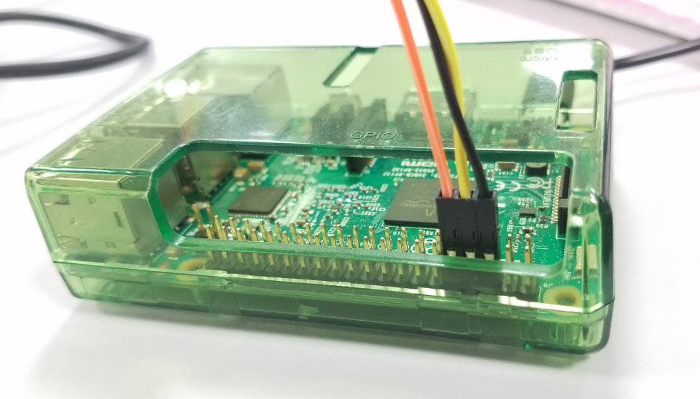
1-1. Connect jumper wires to USB-Serial cable for Tx, Rx, and GND.

1-2. Connect the other side of jumper wires to Raspberry Pi’s GPIO pins. Check this useful site for pinout.

1-3. Connect USB-Serial cable to USB port on PC


2. Setting up terminal emulator on Windows PC
To send and receive serial data, let’s install and setup a terminal emulator program on PC.

2-1. Download and install Termite.

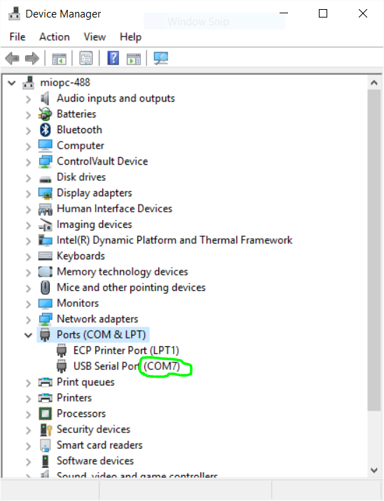
2-2. Open “Device Manager” and check the COM port number USB-Serial cable is using. In the case below, it’s COM7.

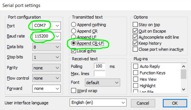
2-3. Launch Termite and click on “Settings” button.

2-4. Select Port number you checked on step 2-2.

2-5. Select “115200” as Baud rate.

2-6. Select “Append CR-LF” in “Transmitted Text”.

2-6. Click on “OK”.


3. Enabling UART on Raspberry Pi
3-1. Open “/boot/config.txt”.

sudo nano /boot/config.txt

3-2. Add the lines below at the end of the file.

# Enable UART
enable_uart=1

3-3. Reboot.

sudo reboot

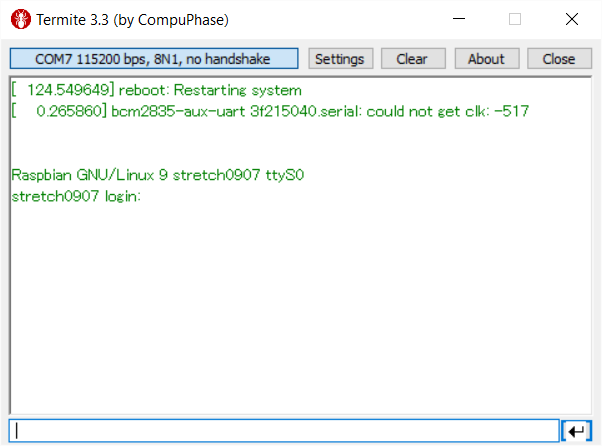
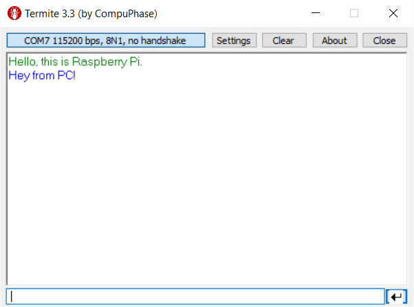
3-4. Check the output of Termite on PC. It should be something like this:


4. Disabling console service
Now, UART connection between Raspberry Pi and PC is established. However, Raspberry Pi’s UART is used by console by default as you saw in the output on step 3-4. So, the next step is to disable the console.

4-1. Disable serial-getty service.

sudo systemctl disable serial-getty@ttyS0.service
4-2. Open “/boot/cmdline.txt”.
sudo nano /boot/cmdline.txt

4-3. Remove “console=serial0,115200”, then save the file.

4-4. Reboot.
sudo reboot


5. Setting up terminal emulator on Raspberry Pi
To send and receive data on Raspberry Pi, we’ll use minicom, a text-based terminal emulator.

5-1. Install minicom.

sudo apt-get install minicom -y

5-2. Type below to launch minicom and connect to UART.

minicom -b 115200 -o -D /dev/ttyS0

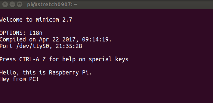
You should see like below:

Welcome to minicom 2.7

OPTIONS: I18n 
Compiled on Apr 22 2017, 09:14:19.
Port /dev/ttyS0, 21:13:28

Press CTRL-A Z for help on special keys


6. Test
Type something in minicom and Termite. If everything is fine, you should see like below.

– Termite on Windows PC

– minicom on Raspberry Pi

  • If you want to see what you typed on minicom, turn on Local Echo by typing Ctrl-A, then E. (which I did)
  • You can exit minicom by typing Ctrl-A, and X, then select “Yes”.


Waking Up Raspberry Pi Using Reset Pin


This post shows steps to wake up Raspberry Pi 3 from other Raspberry Pi by using RUN (reset) pin.

Background: I was looking for a way to wake up my Raspberry Pi 3 from other device and found the information below,

  • Resetting the board while in halt state wakes Raspberry Pi up [1]
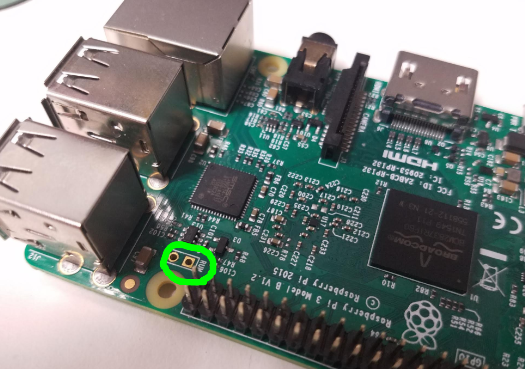
  • Raspberry Pi 3 has reset pin, which is labeled as ‘RUN’ [2]

As described in [1] and [2], momentarily shorting ‘RUN’ pin with GND causes a reset and it also wakes up Raspberry Pi if it’s in halt state. I found many people have implemented a reset button by using “Normally Open” (NO) / “Momentary-ON” button switch [3] [4] , but my intention was to control the reset pin from the other device. So, I decided to connect ‘RUN’ pin to the other device’s GPIO to control it. I chose another Raspberry Pi as the ‘other device’ for quick test purpose so that I don’t need to worry about the difference of logic level, etc.


Here is the list of contents of this post.

Contents
– Assumptions
– Steps
1. Wiring boards
2. GPIO control
3. Put Raspberry Pi 3 into Halt state
4. Test
– Summary
– Troubleshoot
– Reference


Assumptions


Steps
1. Wiring boards
1-1. Since the headers for the reset pins are not installed by default, solder it first.

\

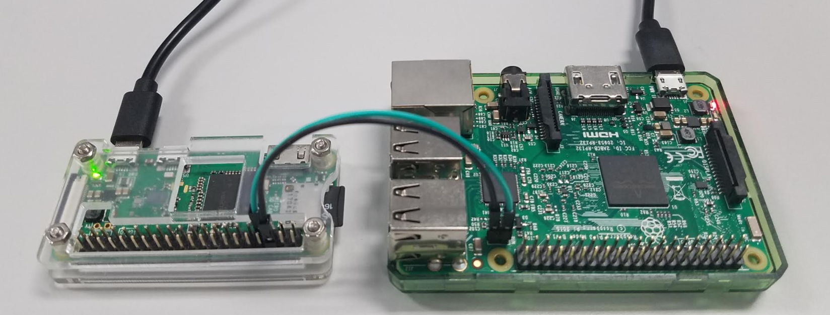
1-2. Connect RUN pin and a GPIO pin between the two boards. I connected RUN with pin#7 on Pi Zero, but any available GPIO should work.

1-3. Connect GND pins between the two boards to match the ground voltages. I used pin#6 on Pi Zero, but any other GND pin should work.


2. GPIO control
2-1. Boot up Raspberry Pi Zero W and login.

2-2. Launch python interactive shell by typing ‘python’.

$ python
Python 2.7.9 (default, Sep 17 2016, 20:26:04) 
[GCC 4.9.2] on linux2
Type "help", "copyright", "credits" or "license" for more information.
>>> 

2-3. Import GPIO library and set GPIO mode.

import RPi.GPIO as gpio
gpio.setmode(gpio.BOARD)

2-4. Set pin#7 as output and initialize the state as HIGH.

gpio.setup(7, gpio.OUT, initial=gpio.HIGH)

2-5. Type three lines below to define a function to momentarily output LOW.

def reset():
    gpio.output(7, gpio.LOW)
    gpio.output(7, gpio.HIGH)

Note that the line 2 and 3 need an indentation at the beginning.

2-6. After entering line 3 above, press enter again to finish the function definition. The output should be like:

>>> def reset():
...     gpio.output(7, gpio.LOW)
...     gpio.output(7, gpio.HIGH)
... 
>>>


3. Put Raspberry Pi 3 into Halt state
3-1. Boot up Raspberry Pi 3 and login.

3-2. Type below so that it goes to halt state.

sudo shutdown -h now


4. Test
4-1. Go back to python interactive shell on Raspberry Pi Zero and call ‘reset()’ function.

>>> reset()

If everything is fine, Raspberry Pi 3 should boot up from halt state.


Summary
I used Raspberry Pi Zero for quick test purpose. If you intend to connect other board, please check the electrical specs such as logic levels, to avoid any damage to the boards.


References
1. Embedded Linux Wiki / RPI safe mode / Wake from Halt

2. Embedded Linux Wiki / RPi Low-level peripherals / P6 header

3. Making a Reset Switch for your Rev 2 Raspberry Pi

4. Reset button switch off my Raspberry Pi3